Converting a Kawai KSP-30 to pure MIDI
Posted on in Hacks • 594 words • 3 minute read
My Kawai KSP-30 digital piano has been on its last leg for some time now. To get it to work at all, I had to unplug the amplification circuit whose interface on the main PCB was burnt out. Of course is wasn’t of much use by itself after that bit of crude surgery but worked fine as a midi keyboard.
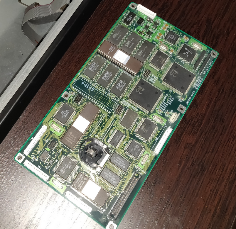
Figure 1: The main PCB.
There must have been some creeping currents because the piano got more and more unreliable requiring hectic powercycling to boot and finally not booting at all. Looking for spare parts on eBay didn’t bring up anything so I decided to scan the keyboard directly with a micro-controller and do away with the rest of the innerts of my trusty Kawai entirely.
First I had to find out how the keyboard matrix was scanned. Luckily I had a logic analyzer lying around to test the ports on the keyboard connector 1
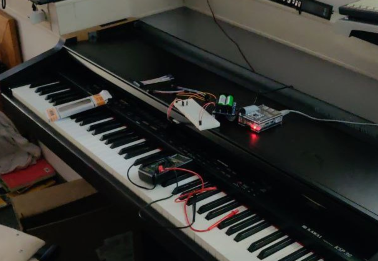
Figure 2: Figuring out the keyboard matrix.
Furthermore, I found the service manual for the KSP on archive.org
and with a little trial and error was able to puzzle it together.
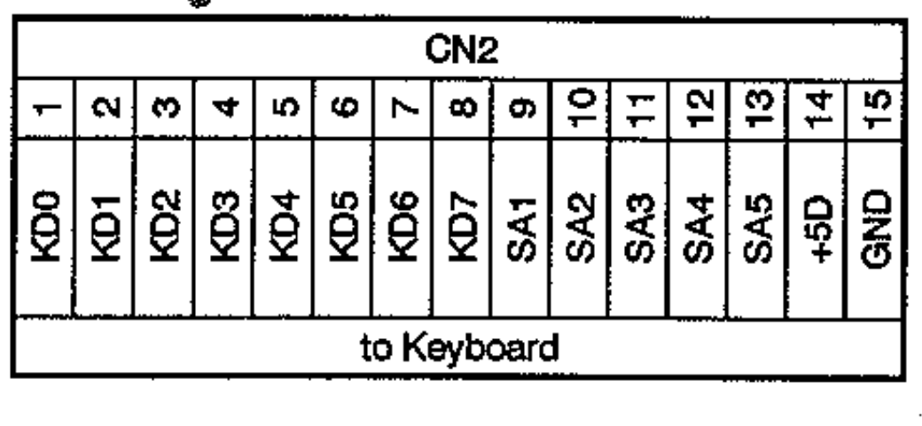
Figure 3: The keyboard connector.
The keyboard matrix has eight columns that can be read through KD0
through KD7 2. To scan all 88 keys three multiplexers
are employed that can be enabled individually by the SA4 and SA6
ports (see figure above). The other three SAX connectors select one
of eight rows through the currently enabled multiplexer. Because the
piano is velocity sensitive, each key actually has two sensors with
one triggered shortly before the other. The time difference between
these signals can be measured to obtain the key velocity. Therefore
the KDX ports are split into two groups S1 and S2 that
correspond to the two triggers.
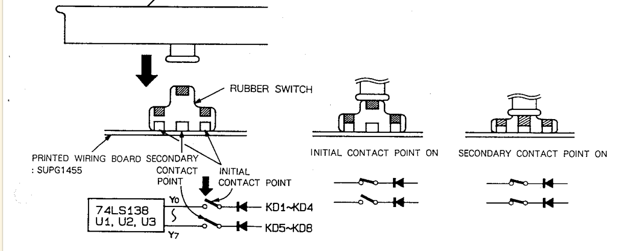
Figure 4: The two-switch mechanism.
Putting all this together one arrives at the following matrix.

In practice one just cycles through the multiplexers while running a counter to obtain the correct note because they are consecutive.
Having ascertained all this knowledge I began the realization of the actual project by sawing out the port for the keyboard connector from the PCB because the connector is not compatible with the usual jumper spacings.

Then I soldered jumper cables to one side of the connector (a real hack job :P) and done was my not-too-fragile interface which I promptly connected to an Arduino Nano clone I had to spare.

And finally the nasty hardware part was done and I could begin to prototype the software on the Nano while waiting for a Pro Micro with native USB capabilities to arrive. It suffices to say that it worked :) with key velocity and all. After the Pro Micro arrived I even got the sustain pedal to work :).
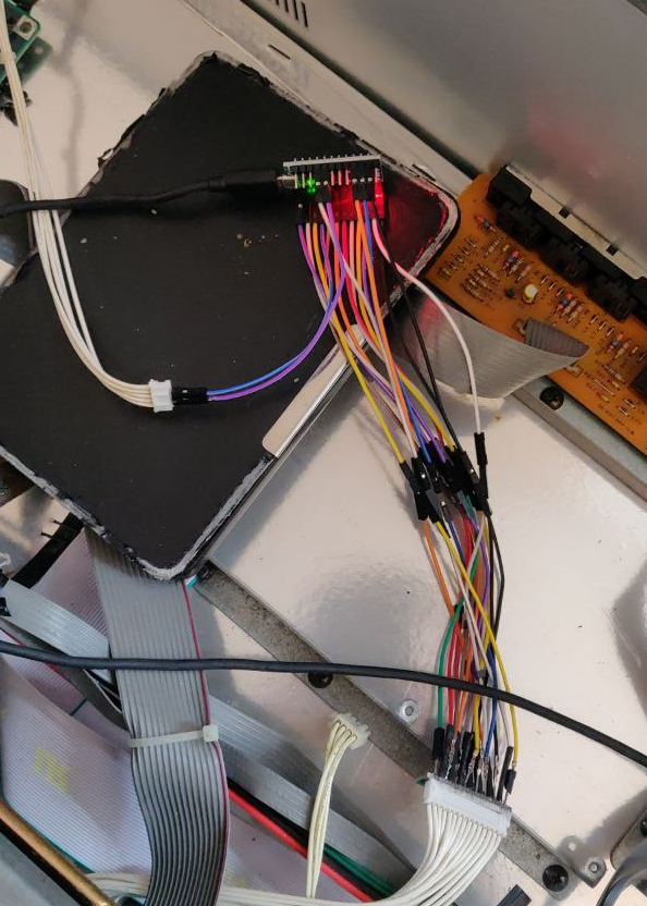
Figure 5: The final assembly.
With the Pro Micro set up I went on to calibrate the key sensitivity which was less of a hassle than I thought and the project was finished. Happily I went back to making music ever after.
The end.
Of course there remains some cleanup to be done (datatypes in the source code). Most urgently I want to implement release velocity. You can find the code and my personal documentation for the project3 over on GitHub.
Maybe this was of interest you. If not, then thanks for reading this far anyways :P.